Introduction Fabric pilling, which happens from wear and friction, is a common issue affecting fabric…
Tensile Tester – TESTEX Instruction Manual
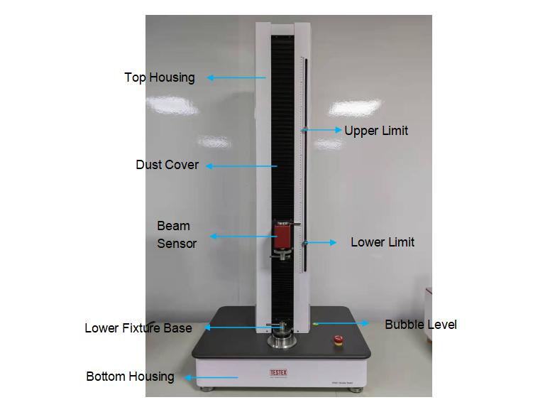
Tensile Tester & Universal tensile testing machine: The equipment is used to test the tensile, bursting, tearing, and peeling properties of fabrics, plastics, paper, leather, etc.
It can be equipped with a pneumatic stretching fixture, manual stretching fixture, bursting fixture, etc. In the configured computer software, you can make more complete settings for the entire test process and display more specific test results (report statistics, graphs, etc.), such as reciprocating test, tear test, peel test, break test, suture slip, and other tests.
Table of Contents
Tensile Tester Testing Standards
The device supports but is not limited to the following standards:
| ISO 3377-1:2011 | ISO 3377-2:2016 | ISO 13934-1:2013 | ISO 13934-2:2014 |
| ISO 13935-1:2014 | ISO 13935-2:2014 | ISO 13936-1:2004 | ISO 13936-2:2004 |
| ISO 13937-2:2000 | ISO 13937-3:2000 | ISO 13937-4:2000 | ISO 20932-1:2018 |
| ISO 4674-1:2016 | ISO 9073-3:1989 | ISO 9073-4:2021 | ISO 2062:2009 |
| ASTM 5034-09:2017 | ASTM 5035-11:2019 | ASTM D4964-96 | ASTM D1683 |
| ASTM D1683M-17 | ASTM D6797-15 | GB/T 3917.5-2009 | GB/T 3923.1-2013 |
| GB/T 3917.3-2009 | GB/T 19976-2005 | FZ/T 01030-2016 |
Tensile Tester Operating Environment
This unit is intended to be used in a residential, commercial, and light industrial environment as laid down in BSEN 50081-1 and BSEN 50082-1.
The following gives examples of locations in which the instrument might be located; workshops, laboratories, and service centers. Locations that are considered to be commercial or light industrial.
- Temperature: 25±5°C
- Humidity: 30%-65%
- Altitude < 2000 m above sea level
- And it is intended to be stored in a temperature range of -25°C~40°C
Tensile Tester Specifications
- Maximum test force
- Testing machine level
- The maximum stroke of the transverse beam
- Transverse beam stroke accuracy
- Range of transverse beam speed adjustment
- Relative error of speed accuracy
- Test force measurement range
- Relative error of test force indication
- Data transmission
Tensile Tester Test Process
Check before boot
Check whether the power plug of the host is inserted firmly.
If there is a Pneumatic fixture, check whether the air supply pipe is firmly inserted, and check whether the air pressure of the air pump is between 0.4 and 0.7 MPa.
Check whether the upper and lower clamps of all samples are installed stably.
Check after boot
Adjust the position of the moving beam -> installation fixture -> adjust the position of the lower limit, ensure that when the Beam runs down to the lower limit and stops, the distance between the jaws is not less than 5mm.
Press the sensor with your finger to see if there is any change in the display; if there is no change, check if the sensor wire is well plugged in and not damaged. If you feel that the force value is not accurate, see if you have selected the correct force channel (page 42 – Sensors); if the channel is correct, find a weight of 20~80% of the sensor range and calibrate it. See (page 28 – item 5) for calibration procedures.
Start testing
Select the test standard, check the stop conditions, and clear the display date. Set the upper and lower limit positions.
Check whether the sample meets the standard requirements after the test, such as the breaking position of the sample, whether there is slippage in the jaws, etc., Subjectively judge whether to accept the test result.
Save test data and output test report.
Tensile Tester Test Parameters
The control parameters are shown below. They are mainly used to set sensors and control related system parameters.
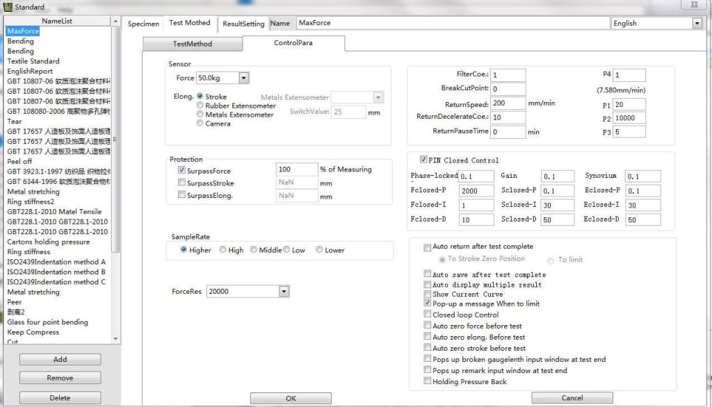
Sensors: Selection of force and displacement sensors
Direction: whether the force, stroke, and displacement values are negative or absolute. When the force or displacement is found, the deformation needs to be both positive and negative. This setting needs to be modified.
Protection: When the current value exceeds the protection value will automatically shut down, selected to enable the protection
Sampling rate: the number of sampling points per second, for a long time constant load test can choose a lower sampling rate
Power Resolution: The higher the resolution, the higher the accuracy
Filter coefficient: filter out unstable data, 0 or 1 that does not filter
Fracture removal points: the final sample points to remove the sample fracture
ReturnSpeed: Set the speed of the return position;
ReturnDecelerateCoe: The deceleration coefficient is 10 when the displacement reaches 10 mm, indicating that the deceleration begins when the displacement reaches 10 mm;
ReturnPauseTime: Waiting time when automatic return is completed;
P1: The fracture control parameters are judged systematically;
P2: The corresponding coefficient of speed closed-loop control;
P3: Speed closed-loop control speed adjustment time;
P4: When the load is constant and the stress is constant, the starting speed of pressure is needed after the force decreases, and the speed is the maximum speed/100*P4.
Auto return after test complete: Check this item, after the test is completed, the machine will automatically return to position. There are two choices for the stop position of return: displacement 0 point or limit position (i.e. encounter limit switch).
Pop-up a message When to limit: Check this item, the machine will jump out of the prompt box when it reaches the limit position.
Closed loop control: If this item is checked, the control system will adjust the running speed of the machine in real time according to the running condition of the machine, so as to match the set speed with the actual running speed. When calibrating speed, this item cannot be checked, otherwise, the speed will not be calibrated accurately. In addition, when there is no displacement encoder, do not check this item, otherwise, the machine speed will be out of control.
Auto zero force before the test: Check this item. When you click on the test, the force will be cleared automatically.
Auto zero elong before the test: Check this item. When you click on the test, the elong will be cleared automatically.
Auto zero stroke before the test: Check this item. When you click on the test, the stroke will be cleared automatically.
Pops up broken gauge lenth input window at test end: Check this item, after the test is completed, an input window will pop up, which can be used to calculate the elongation and shrinkage of the material after breaking.
Pops up remark input window at test end: Check this item, and when the test is completed, an input window will pop up for input notes.
Holding Pressure Back: Check this item, when the force is fixed and the stress is fixed, if the force is greater than the set value, the machine will do the decompression movement. If this item is not checked, the power exceeds the set value, and the machine just stops. This setting can cause fluctuations in power, usually without checking.
Tensile Tester Software
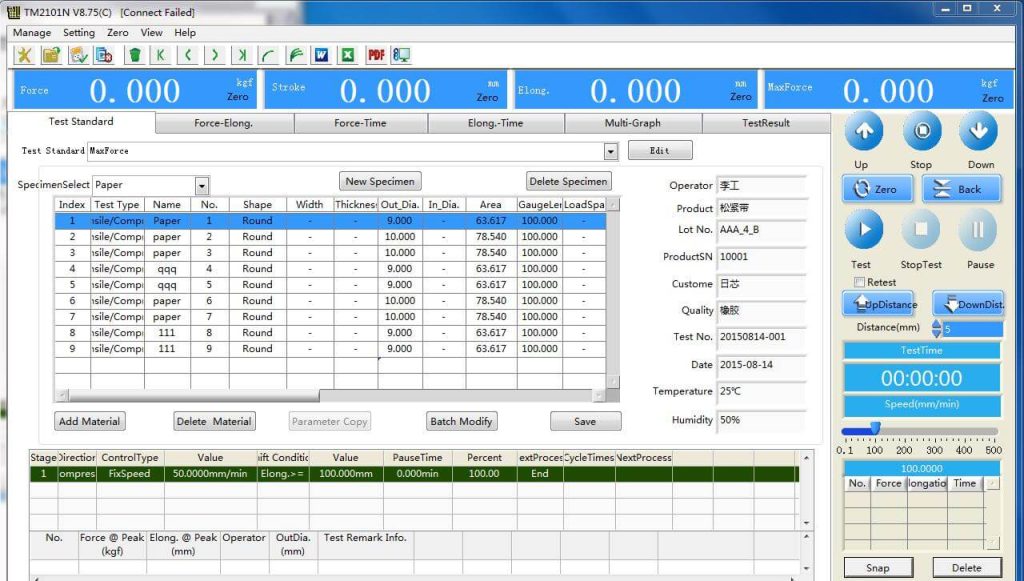
A complete test process consists of three steps: setting up before the test, executing the test, and getting test results.
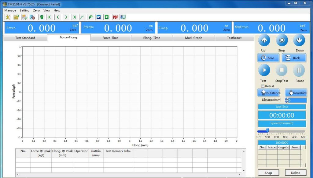
The implementation of testing: Switch to the interface before testing and select a test standard. The test will be tested according to this standard. At the end of the test, the corresponding results will be output according to this standard.
Start the test to indicate that the test is currently in progress, wait for the test to end automatically or end it manually.
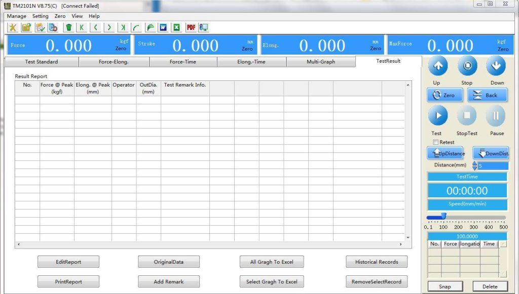
- PrintReport: Print simple result report with software;
- EditReport: Editing Simple Report with Software;
- All Gragh to Excel: output all curves to an excel document;
- Select Gragh to excel: output the selected curve to an excel document;
- RemoveSelecteRecord: If you want to remove a record from the test results, you can select the record first, and then click the button. Note that the button simply removes the data from the test results and does not delete the data from the test database.
- OriginalData: Output the original data to Excel. Note: This function is only valid when a single curve is displayed.
- Historical Records: Archives database interface mainly consists of three parts:
- All Test Data Info: Display all test data related information stored in the file, so that customers can easily query and retrieve the data in the file.
- Query Test Data: Users can query test data according to test time, number, batch, material and standard, and output test results according to the query results.
- Current Result TestInfo: The test information corresponding to the current output result is displayed.
Tensile Tester Maintenance
Need to clean up after each test. Keep the equipment clean.
The fixture should be coated with anti-rust oil for storage after use.;
The replacement of the sensor or the plugging and unplugging of the cable must be performed after the power is turned off. If the sensor connection end is suspended, the amplifier and AD conversion circuit will be easily damaged due to static electricity.
The instrument needs to calibrate the load cell periodically to ensure the accuracy of the measured value of the instrument.
Lubricate the moving parts regularly.
If the instrument fails, it should be repaired by professionals or the manufacturer. Spare parts must be replaced according to the original model.
Related Posts


This Post Has 0 Comments